EP100+LRX-E
Details
Details
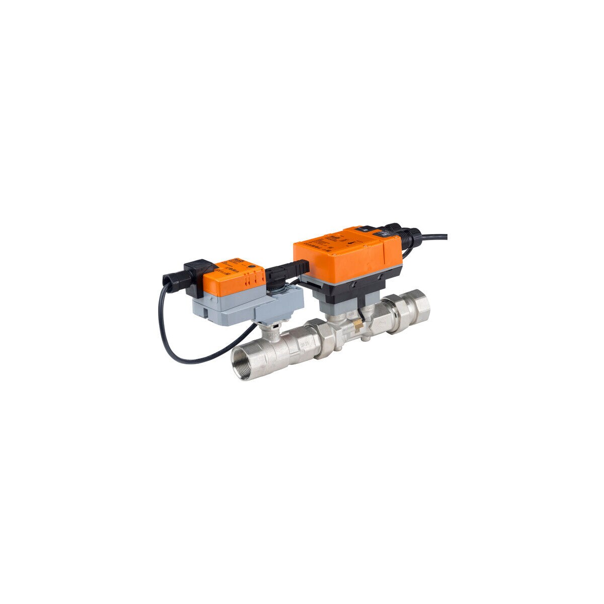
EP100+LRX-E 1 in. Electronic Pressure Independent Valve (ePIV), 18.2 GPM, Non-Spring Return, 24 VAC/DC
Built-in ultrasonic flow meter; for chilled or hot water, up to 60% glycol max. Holds the set flow as system pressure changes, within its differential pressure range.
Key Features
- Max flow: 18.2 GPM
- Differential pressure range: 5 to 50 psi 1 to 50 psi, see "Flow Reduction Chart"
- Close-off: 200 psi
- Communication: BACnet MS/TP, Modbus RTU, MP-Bus
Product Specifications
| Manufacturer | Belimo |
|---|---|
| Model | EP100LRXE (EP100+LRX-E) |
| Nominal voltage | AC/DC 24 V |
| Nominal voltage frequency | 50/60 Hz |
| Nominal voltage range | AC 19.2 to 28.8 V / DC 21.6 to 28.8 V |
| Power consumption in operation | 3.5 W |
| Power consumption in rest position | 1.3 W |
| Transformer sizing | 6 VA |
| Connection supply/control | Cable 3 ft. (1 m), 6 x 0.75 mm2 |
| Conductors, cables | Power supply AC/DC 24 V: cable length <100 m |
| Cable length | 3 ft (1 m) |
| Electrical connection | 18 AWG plenum cable |
| Overload Protection | electronic thoughout 0 to 90 deg rotation |
| Communicative control | BACnet MS/TP Modbus RTU MP-Bus |
| Valve size [mm] | 1" (25) |
| Operating range Y | 2 to 10 V |
| Operating range Y variable | 0.5 to 10 V |
| Operating range Y note | 4 to 20 mA w/ ZG-R01 (500 Ω, 1/4 W resistor) |
| Input impedance | 100 kΩ (0.1 mA), 500 Ω |
| Operating modes optional | VDC variable |
| Position feedback U | 2 to 10 V |
| Position feedback U note | Max. 1 mA |
| Position indication | Mechanical, pluggable |
| Running Time (Motor) | 90 s |
| Sound power level motor | 35 dB(A) |
| V'max adjustable | 25 to 100% of V'nom |
| Control accuracy | +/-5% (of 25 to 100% V'nom) |
| Configuration | via NFC, Belimo Assistant 2 |
| Fluid | chilled or hot water, up to 60% glycol max (open loop/steam not allowed) |
| Fluid temperature | 14 to 250 deg F (-10 to 120 deg C) |
| Close-off pressure | ∆ps 200 psi |
| Differential pressure | 5 to 50 psi 1 to 50 psi, see "Flow Reduction Chart" |
| Flow characteristic | equal percentage or linear |
| Leakage rate | 0% leakage |
| Pipe connection | Internal thread NPT (female) |
| Installation orientation | upright to horizontal (in relation to the spindle) |
| Servicing | maintenance-free |
| Manual override | external push button |
| Inlet Length to Meet Specified Measurement ≥0 | ≥0 x DN (according to EN 1434-4:2022) |
| Measured values | Flow |
| Temperature sensor | Pt1000 - EN 60751, 2-wire technology, inseparably connected integrated in flow sensor |
| Measuring accuracy absolute temperature | +/-1.1 deg F @ 50 deg F (+/-0.6 deg C @ 10 deg C) (Pt1000 EN60751 Class C) +/-1.35 deg F @ 140 deg F (+/-0.75 deg C @ 60 deg C) (Pt1000 EN60751 Class C) |
| Measuring principle | Ultrasonic flow measurement |
| Measuring accuracy flow | +/-2% |
| Measurement repeatability | +/-0.5% (Flow) |
| Sensor technology | Ultrasonic with glycol and temperature compensation |
| Degree of protection NEMA/UL | NEMA 2 |
| Housing | UL Enclosure Type 2 |
| Pressure equipment directive | CE according to 2014/68/EU |
| Quality Standard | ISO 9001 |
| UL 2043 Compliant | Suitable for use in air plenums per Section 300.22(C) of the NEC and Section 602 of the IMC |
| Rated impulse voltage supply / control | 0.8 kV |
| Ambient humidity | Max. 95% RH, non-condensing |
| Ambient temperature | -22 to 122 deg F (-30 to 50 deg C) |
| Storage temperature | -40 to 176 deg F (-40 to 80 deg C) |
| Valve body | forged brass |
| Body finish | nickel-plated |
| Flow measuring pipe | forged brass |
| Closing element | Stainless steel |
| Stem | stainless steel |
| Stem seal | EPDM (lubricated) |
| Seat | PTFE |
| Characterized disc | TEFZEL® |
| O-ring | EPDM |
| Ball | stainless steel |
| Operating mode | The HVAC performance device is comprised of three components: characterized control valve (CCV), measuring pipe with flow sensor and the actuator itself. The adjusted maximum flow (V'max) is assigned to the maximum control signal (typically 100%). The HVAC performance device can be controlled via communicative signals. The fluid is detected by the sensor in the measuring pipe and is applied as the flow value. The measured value is balanced with the setpoint. The actuator corrects the deviation by changing the valve position. The angle of rotation α varies according to the differential pressure through the control element (see flow curves). |
| Control characteristics | The fluid velocity is measured in the measuring component (sensor electronics) and converted to a flow rate signal. The control signal Y corresponds to the power Q via the exchanger, the volumetric flow is regulated in the EPIV. The control signal Y is converted into a linear characteristic curve and provided with the V'max value as the new reference variable w. The momentary control deviation forms the control signal Y1 for the actuator. The specially configured control parameters in connection with the precise flow rate sensor ensure a stable quality of control. They are however not suitable for rapid control processes, i.e. for domestic water control. U5 displays the measured flow as voltage (factory setting). Parametrizing V'max with ZTH: U5 refers to the respective V'nom, i.e. if V'max is e.g. 50% of V'nom, then Y = 10 V, U5 = 5 V. Parametrizing V'max with PC-Tool: In the PC-Tool, the maximum flow rate to which U5 refers can be set individually. If V'max is changed (e.g. to 70% V'nom), the U5 flow range is also automatically changed to the same value (e.g. 70% V'nom: U5 = 10 V). This adjustment can be reversed by entering a value manually (U5 flow range = 100%: U5 refers to V'nom). As an alternative, U5 can be used for displaying the valve opening angle. |
| Fluid temperature measurement | The integrated temperature sensor within the flow sensor continuously measures the medium's temperature. This measured value can be accessed through the bus system or via the analog feedback signal U. Additionally, the current temperature reading is displayed in the Belimo Assistant 2 App. |
| Creep flow suppression | Given the very low flow speed in the opening point, this can no longer be measured by the sensor within the required tolerance. This range is overridden electronically. Opening valve The valve remains closed until the flow required by the control signal DDC corresponds to 1% of V'nom. The control along the flow characteristic is active after this value has been exceeded. Closing valve The control along the flow characteristic is active up to the required flow rate of 1% of V'nom. Once the level falls below this value, the flow rate is maintained at 1% of V'nom. If the level falls below the flow rate of 0.5% of V'nom required by the control signal DDC, then the valve will close. |
| Converter for sensors | Connection option for a sensor (active or with switching contact). In this way, the analog sensor signal can be easily digitized and transferred to the bus systems BACnet, Modbus or MP-Bus. |
| Control signal inversion | This can be inverted in cases of control with an analog control signal. The inversion causes the reversal of the standard behavior, i.e. at a control signal of 0%, is equal to V'max, and the valve is closed at a control signal of 100%. |
| Hydronic balancing | With the Belimo tools, the maximum flow rate (equivalent to 100% requirement) can be adjusted on-site, simply and reliably, in a few steps. If the device is integrated in the management system, then the balancing can be handled directly by the management system. |
| (hybrid mode) | Bus can be used for the communicative position feedback. |
| Manual override | Manual control with push-button possible - temporary. The gear train is disengaged and the actuator decoupled for as long as the button is pressed. |