22PE-5XUHKH
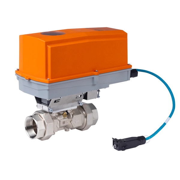
Details
Details
22PE-5XUHKH 2 in. Thermal Energy Meter, 100 GPM Nominal Flow, Humidistat heater
Measures flow and supply/return temperature difference to calculate heating or cooling energy. Set up as a heat, cooling, or combined meter with Belimo Assistant 2. Size it to its nominal flow, not the pipe.
Key Features
- Flow range: 1.0 to 132.1 GPM
- Pressure drop: 7.3 psi at nominal flow
- Heater: humidistat heater
Product Specifications
| Manufacturer | Belimo |
|---|---|
| Model | 22PE5XUHKH (22PE-5XUHKH) |
| Pipe size | 2 in. (DN 50) |
| Nominal flow (qp) | 100 GPM |
| Highest flow (qs) | 132.1 GPM |
| Lowest flow (qi) | 1.0 GPM |
| Pressure drop at qp | 7.3 psi |
| Additional features | Humidistat heater |
| Nominal voltage | AC/DC 24 V |
| Nominal voltage frequency | 50/60 Hz |
| Nominal voltage range | AC 19.2 to 28.8 V / DC 21.6 to 28.8 V |
| Power consumption AC | 3 VA |
| Power consumption DC | 1.5 W |
| Power consumption PoE | 2.2 W |
| Connection supply | cable 3 ft (1 m), 6x 0.75 mm2 |
| Connection Ethernet | RJ45 socket |
| Power over Ethernet PoE | DC 37 to 57 V IEEE 802.3af/at, Type 1, Class 3 11 W (PD13W) |
| Conductors, cables | Power supply AC/DC 24 V: cable length <100 m, no shielding or twisting required Power supply PoE: shielded cables recommended |
| Annual energy consumption | With external energy supply 13.2 kWh |
| Communication | BACnet/IP BACnet MS/TP Modbus TCP Modbus RTU MP-Bus |
| Communication note | M-Bus via Converter G-22PEM-A01 |
| Number of nodes | BACnet / Modbus see interface description MP-Bus max. 8 (16) |
| Medium | Water Water-glycol mixture |
| Configuration | via NFC, Belimo Assistant 2 via integrated web server |
| Voltage output | 1 x 0 to 10 V, 0.5 to 10 V, 2 to 10 V |
| PN | 25 |
| Body Pressure Rating | 360 psi |
| Pipe connection | External thread according to ISO 228-1 |
| Servicing | maintenance-free |
| Inlet Length to Meet Specified Measurement ≥ to | to 0 x DN (according to EN1434-4:2022) |
| Type of contact | Normally closed contact |
| Heating output | 21 W |
| Inrush current | Max. 2.5 |
| Settings | 65% RH fixed |
| Switching differential humidistat (humidity) | 4% RH (+/-3% tolerance) |
| Heater | Aluminium profile, anodized |
| Sensor element | Thermobimetal |
| Type of contact | Normally closed contact |
| Heating output | 21 W |
| Inrush current | Max. 2.5 |
| Thermostat range | 14 to 122 deg F (-10 to 50 deg C) (factory setting 86 deg F (30 deg C)) |
| Switching differential thermostat | 7 K (+/-4 K tolerance) |
| Heating element | Positive temperature coefficient resistor (PTC), self-regulating, temperature-limiting |
| Heater | Aluminium profile, anodized |
| Measured values | Flow Temperature |
| Measuring fluid | chilled or hot water, up to 60% glycol max (open loop/steam not allowed) |
| Measuring principle | Ultrasonic flow measurement |
| Behavior at flow rate greater than qs | Limitation at 2.5 x qp |
| Dynamic range qi:qp | 1:100 |
| Measuring accuracy flow | +/-2% (of 20 to 100% qp) @ 68 deg F (20 deg C) / glycol 0% vol. |
| Measuring accuracy flow note | EN 1434 Class 2 @ 59 to 248 deg F (15 to 120 deg C) |
| Temperature sensor | Pt1000 - EN 60751, 2-wire technology, inseparably connected Cable length external sensor T1: 3 m |
| Protection class IEC/EN | III, Protective Extra-Low Voltage (PELV) Logic module: IP54 (with grommet A-22PEM- A04) Sensor module: IP65 |
| Degree of protection NEMA/UL | NEMA 4 |
| Pressure equipment directive | CE according to 2014/68/EU |
| EMC | CE according to 2014/30/EU |
| Certification IEC/EN | IEC/EN 60730-1:11 and IEC/EN 60730-2-15:10 |
| Quality Standard | ISO 9001 |
| Type of action | Type 1 |
| Rated impulse voltage supply | 0.8 kV |
| Pollution degree | 3 |
| Ambient humidity | Max. 95% RH, non-condensing |
| Ambient temperature | -22 to 122 deg F (-30 to 50 deg C) |
| Fluid temperature | -20 to 120 deg C (-4 to 250 deg F) Frost protection must be guaranteed at fluid temperatures <2 deg C (<36 deg F) |
| Storage temperature | -40 to 176 deg F (-40 to 80 deg C) |
| Cable | PVC |
| Fluid wetted parts | Brass nickel-plated, Brass, Stainless steel, PEEK, EPDM |
| Belimo cloud | The "Terms of Use for Belimo Cloud Services" in their currently valid version apply to the use of cloud services. Note: The connection to the Belimo Cloud is permanently available. Activation takes place via web server or Belimo Assistant 2. |
| Measuring accuracy | Measuring accuracy for water (glycol 0% vol.): +/-2% (@ 20 to 100% qp) At a temperature range of 15 to 120 deg C. Measuring accuracy for water + glycol (glycol 0 to 60% vol.) +/-5% (@ 20 to 100% qp) +/-0.01 qp, but not more than 30% of q (@ qi...20% qp) At a temperature range of -20 to 120 deg C. 1 LED display green On: Device starting up Flashing: In operation (Power ok) Off: No power 2 Flow direction 3 NFC interface |
| Permissible installation orientation | The sensor can be installed upright to horizontal. The sensor may not be installed in a hanging position. |
| Installation in return | Installation in the return is recommended. |
| Dimensioning | The thermal energy meter is dimensioned to the nominal flow (qp). The flow rate may increase to the highest flow (qs) for a short time (<1h/day). |
| Inlet section | There are no requirements for straight inlet sections prior to the flow sensor. Product has been tested to and fulfills the requirements of EN1434-4:2022 |
| Water quality requirements | The water quality requirements specified in VDI 2035 must be adhered to. |
| Servicing | Thermal energy meter are maintenance-free. Before any service work on the thermal energy meter is carried out, it is essential to isolate the thermal energy meter from the power supply (by unplugging the electrical cables if necessary). Any pumps in the part of the piping system concerned must also be switched off and the appropriate slide valves closed (allow all components to cool down first if necessary and always reduce the system pressure to ambient pressure level). The system must not be returned to service until the thermal energy meter has been correctly reassembled in accordance with the instructions and the pipeline has been refilled by professionally trained personnel. |
| Flow direction | The direction of flow, specified by an arrow on the housing, is to be complied with, since otherwise the flow rate will be measured incorrectly. |
| Avoiding cavitation | To avoid cavitation, the system pressure at the outlet of the thermal energy meter must be a minimum of 14.5 psi (1.0 bar) at qs (highest flow) and temperatures up to 195 deg F (90 deg C). At a temperature of 250 deg F (120 deg C) the system pressure at the outlet of the thermal energy meter must be at least 36.3 psi (2.5 bar). |
| Cleaning of pipes | Before installing the thermal energy meter, the circuit must be thoroughly rinsed to remove impurities. |